
Commercial HVAC System
Abstract
HVAC systems are milestones of building mechanical systems that provide thermal com- fort for occupants accompanied with indoor air quality. HVAC systems can be classified into central and local systems according to multiple zones, location, and distribution. Primary HVAC equipment includes heating equipment, ventilation equipment, and cool- ing or air-conditioning equipment. Central HVAC systems locate away from buildings in a central equipment room and deliver the conditioned air by a delivery ductwork system. Central HVAC systems contain all-air, air-water, all-water systems. Two systems should be considered as central such as heating and cooling panels and water-source heat pumps. Local HVAC systems can be located inside a conditioned zone or adjacent to it and no requirement for ductwork. Local systems include local heating, local air- conditioning, local ventilation, and split systems.
1. Introduction
Heating, ventilation, and air conditioning (HVAC) system is designed to achieve the environ- mental requirements of the comfort of occupants and a process.
HVAC systems are more used in different types of buildings such as industrial, commercial, residential and institutional buildings. The main mission of HVAC system is to satisfy the thermal comfort of occupants by adjusting and changing the outdoor air conditions to the desired conditions of occupied buildings [1]. Depending on outdoor conditions, the outdoor air is drawn into the buildings and heated or cooled before it is distributed into the occupied spaces, then it is exhausted to the ambient air or reused in the system. The selection of HVAC
systems in a given building will depend on the climate, the age of the building, the individual preferences of the owner of the building and a designer of a project, the project budget, the architectural design of the buildings.
HVAC systems can be classified according to necessary processes and distribution process [2]. The required processes include the heating process, the cooling process, and ventilation process. Other processes can be added such as humidification and dehumidification process. These process can be achieved by using suitable HVAC equipment such as heating systems, air-conditioning systems, ventilation fans, and dehumidifiers. The HVAC systems need the distribution system to deliver the required amount of air with the desired environmental condition. The distribution system mainly varies according to the refrigerant type and the delivering method such as air handling equipment, fan coils, air ducts, and water pipes.
2. HVAC system selection
System selection depends on three main factors including the building configuration, the cli- mate conditions, and the owner desire .The design engineer is responsible for considering various systems and recommending more than one system to meet the goal and satisfy the owner of a building. Some criteria can be considered such as climate change (e.g., temperature, humidity, and space pressure), building capacity, spatial requirements, cost such as capital cost, operating cost, and maintenance cost, life cycle analysis, and reliability and flexibility.
However, the selection of a system has some constraints that must be determined. These con- straints include the available capacity according to standards, building configuration, available space, construction budget, the available utility source, heating and cooling building loads
3. Basic components of an HVAC system
The basic components or equipment of an HVAC isfy thermal comfort of space and occupants and below :
- -Mixed-air plenum and outdoor air control
- -Air filter
- -Supply fan
- -Exhaust or relief fans and an air outlet
- -Outdoor air intake
- -Ducts
- -Terminal devices
- -Return air system
- -Heating and cooling coils
- -Self-contained heating or cooling unit
- -Cooling tower
- -Boiler
- -Control
- -Water chiller
- -Humidification and dehumidification equipment
4.Classification of HVAC systems
The major classification of HVAC systems is central system and decentralized or local system. Types of a system depend on addressing the primary equipment location to be centralized as conditioning entire building as a whole unit or decentralized as separately conditioning a specific zone as part of a building. Therefore, the air and water distribution system should be designed based on system classification and the location of primary equipment. The criteria as mentioned above should also be applied in selecting between two systems. Table 1 shows the comparison of central and local systems according to the selection criteria .
| Criteria | Central system | Decentralized system |
|
Temperature, humidity, and space pressure requirements |
Fulfilling any or all of the design parameters |
Fulfilling any or all of the design parameters |
| Capacity requirements |
-Considering HVAC diversity factors to reduce the installed equipment capacity -Significant first cost and operating cost |
- Maximum capacity is required for each equipment -Equipment sizing diversity is limited |
| Redundancy | Standby equipment is accommodated for troubleshooting and maintenance | No backup or standby equipment |
| Special requirements |
-An equipment room is located outside the conditioned area, or adjacent to or remote from the building -Installing secondary equipment for the air and water distribution which requires additional cost |
-Possible of no equipment room is needed -Equipment may be located on the roof and the ground adjacent to the building |
| First cost |
-High capital cost -Considering longer equipment services life to compensate the high capital cost |
-Affordable capital cost |
| Operating cost |
-More significant energy efficient primary equipment -A proposed operating system which saves operating cost |
-Less energy efficient primary equipment -Various energy peaks due to occupants’preference - Higher operating cost |
| Maintenance cost |
Accessible to the equipment room for maintenance and saving equipment in excellent condition, which saves maintenance cost |
Accessible to equipment to be located in the basement or the living space. However, it is difficult for roof location due to bad weather |
| Reliability | Central system equipment can be an attractive benefit when considering its long service life |
Reliable equipment, although the estimated equipment service life may be less |
|
Flexibility |
Selecting standby equipment to provide an alternative source of HVAC or backup | Placed in numerous locations to be more flexible |
Table 1. Comparison of central and local HVAC systems
5. HVAC system requirements
Four requirements are the bases for any HVAC systems . They need primary equipment, space requirement, air distribution, and piping, as shown in Figure 1.
Primary equipment includes heating equipment such as steam boilers and hot water boil- ers to heat buildings or spaces, air delivery equipment as packaged equipment to deliver conditioned ventilation air by using centrifugal fans, axial fans, and plug or plenum fans, and refrigeration equipment that delivers cooled or conditioned air into space. It includes cooling coils based on water from water chillers or refrigerants from a refrigeration process.
Space requirement is essential in shaping an HVAC system to be central or local. It requires
Five facilities as the following:
1- Equipment rooms: since the total mechanical and electrical space requirements range between 4 and 9% of the gross building area. It is preferable to be centrally located in the building to reduce the long duct, pipe, and conduit runs and sizes, to simplify shaft layouts, and centralized maintenance and operation.
2- HVAC facilities: heating equipment and refrigeration equipment require many facilities to perform their primary tasks of heating and cooling the building. The heating equipment requires boiler units, pumps, heat exchangers, pressure-reducing equipment, control air compressors, and miscellaneous equipment, while the refrigeration equipment requires water chillers or cooling water towers for large buildings, condenser water pumps, heat exchangers, air-conditioning equipment, control air compressors, and miscellaneous equip- ment. The design of equipment rooms to host both pieces of equipment should consider the size and the weight of equipment, the installation and maintenance of equipment, and the applicable regulations to combustion air and ventilation air criteria.
3- Fan rooms contain the HVAC fan equipment and other miscellaneous equipment. The rooms should consider the size of the installation and removal of fan shafts and coils, the replacement, and maintenance. The size of fans depends on the required air flow rate to condition the building, and it can be centralized or localized based on the availability, location, and cost. It is preferable to have easy access to outdoor air.
- 4-Vertical shaft: provide space for air distribution and water and steam pipe distribution. The air distribution contains HVAC supply air, exhaust air, and return air ductwork. Pipe distri- bution includes hot water, chilled water, condenser water, and steam supply, and condenser return. The vertical shaft includes other mechanical and electrical distribution to serve the entire building including plumbing pipes, fire protection pipes, and electric conduits/closets.
- 5-Equipment access: the equipment room must allow the movement of large, heavy equip- ment during the installation, replacement, and maintenance.
Figure 1. Horizontal hierarchy representation of HVAC system requirements.
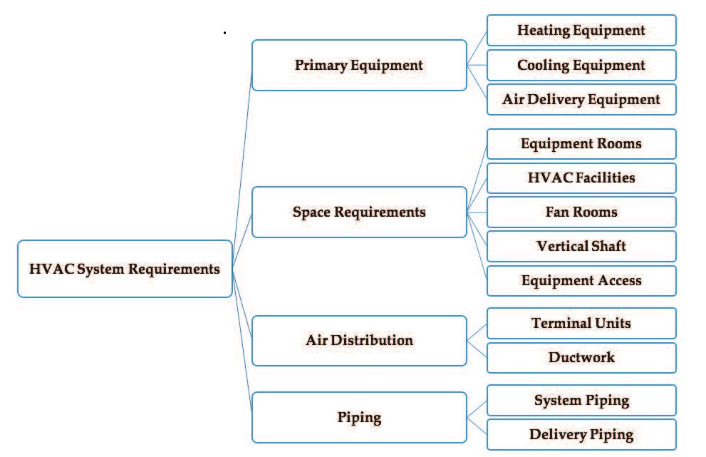
The piping system is used to deliver refrigerant, hot water, cooled water, steam, gas, and condensate to and from HVAC equipment in a direct, quiet and affordable way. Piping sys-tems can be divided into two parts: the piping in the central plant equipment room and the delivery piping. HVAC piping may or may not be insulated based on existing code criteria.
6. Central HVAC systems
A central HVAC system may serve one or more thermal zones, and its major equipment is located outside of the served zone(s) in a suitable central location whether inside, on top, or adjacent to the building . Central systems must condition zones with their equivalent thermal load. Central HVAC systems will have as several control points such as thermostats for each zone. The medium used in the control system to provide the thermal energy sub-classifies the central HVAC system, as shown in Figure 2.
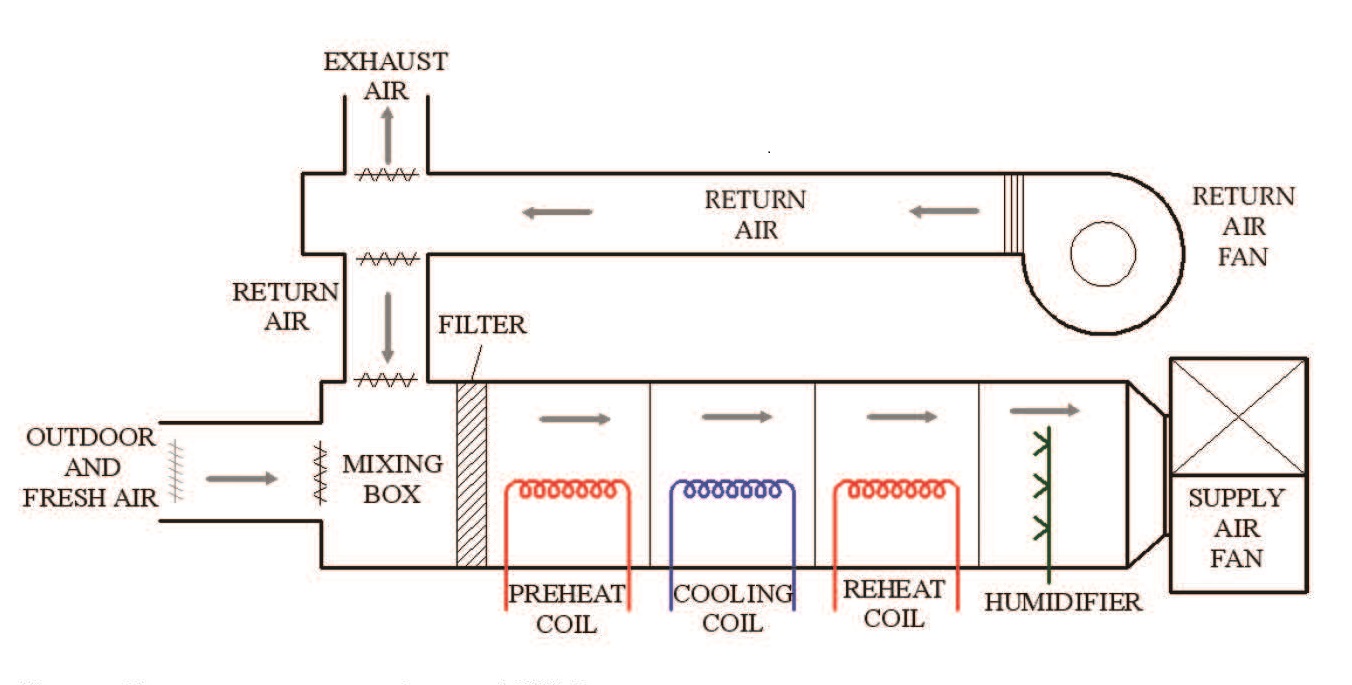
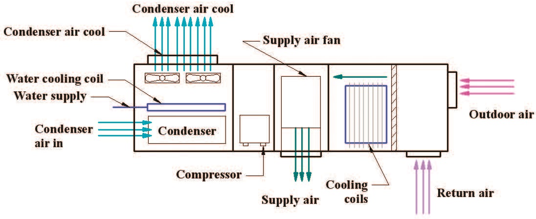
The thermal energy transfer medium can be air or water or both, which represent as all-air systems, air-water systems, all-water systems. Also, central systems include water-source heat pumps and heating and cooling panels. All of these subsystems are discussed below. Central HVAC system has combined devices in an air handling unit, as shown in Figure 3, which contains supply and return air fans, humidifier, reheat coil, cooling coil, preheat coil, mixing box, filter, and outdoor air.
6.1. All-air systems
The thermal energy transfer medium through the building delivery systems is air. All-air systems can be sub-classified based on the zone as single zone and multizone, airflow rate for each zone as constant air volume and variable air volume, terminal reheat, and dual duct.
Figure 2. Horizontal hierarchy representation of the main types of central HVAC systems.
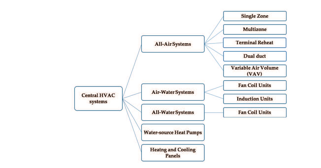
Figure 3. Equipment arrangement for central HVAC system.
6.1.1. Single zone
A single zone system consists of an air handling unit, a heat source and cooling source, dis-tribution ductwork, and appropriate delivery devices. The air handling units can be wholly integrated where heat and cooling sources are available or separate where heat and cooling source are detached. The integrated package is most-commonly a rooftop unit and connected to ductwork to deliver the conditioned air into several spaces with the same thermal zone. The main advantage of single zone systems is simplicity in design and maintenance and low first cost compared to other systems. However, its main disadvantage is serving a single ther-mal zone when improperly applied.
Figure 4. All-air HVAC system for single zone.
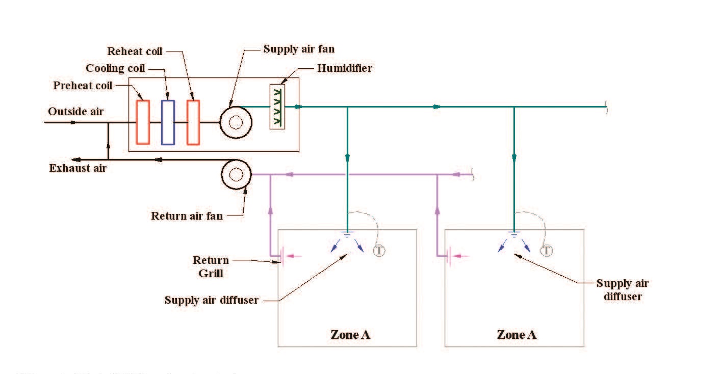
In a single zone all-air HVAC system, one control device such as thermostat located in the zone controls the operation of the system, as shown in Figure 4. Control may be either modu-lating or on–off to meet the required thermal load of the single zone. This can be achieved by adjusting the output of heating and cooling source within the packaged unit.
Although few buildings can be a single thermal zone, a single zone can be found in several applications. One family residential buildings can be treated as single zone systems, while other types of residential buildings can include different thermal energy based on the occupation and building structure. Movements of occupants affect the thermal load of the building, which results in dividing the building into several single zones to provide the required environmental condition. This can be observed in larger residences, where two (or more) single zone systems may be used to provide thermal zoning. In low-rise apartments, each apartment unit may be conditioned by a separate single zone system. Many sizeable single story buildings such as supermarkets, discount stores, can be effectively conditioned by a series of single zone systems. Large office buildings are sometimes conditioned by a series of separate single zone systems.
6.1.2. Multi-zone
In a multi-zone all-air system, individual supply air ducts are provided for each zone in a building. Cold air and hot (or return) air are mixed at the air handling unit to achieve the thermal requirement of each zone. A particular zone has its conditioned air that cannot be mixed with that of other zones, and all multiple zones with different thermal requirement demand separate supply ducts, as shown in Figure 5. Multi-zone all-air system consists of an air handling unit with parallel flow paths through cooling coils and heating coils and
Figure 5. All-air HVAC system for multiple zones.
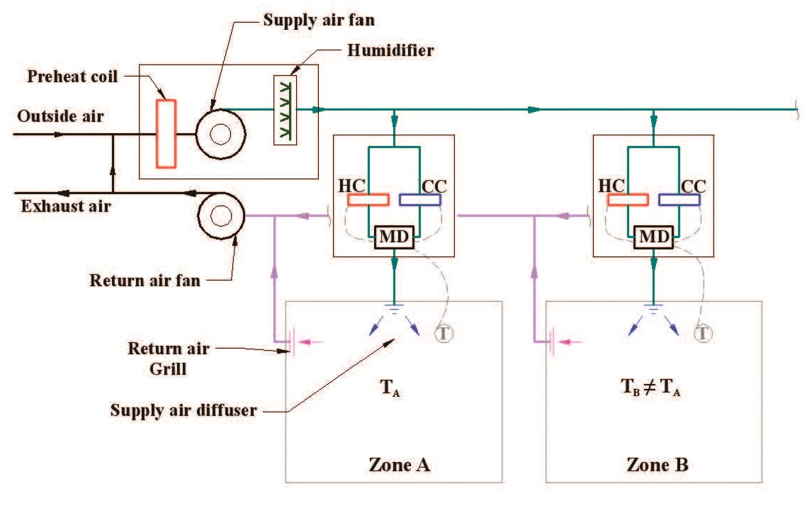
internal mixing dampers. It is recommended that one multi-zone serve a maximum of 12 zones because of physical restrictions on duct connections and damper size. If more zones are required, additional air handlers may be used. The advantage of the multi-zone system is to adequately condition several zones without energy waste associated with a terminal reheat system. However, leakage between the decks of air handler may reduce energy efficiency. The main disadvantage is the need for multiple supply air ducts to serve multiple zones.
6.1.3. Terminal reheat
A terminal reheat all-air system is a multiple zone, which considers an adaptation of single zone system, as shown in Figure 6. This can be performed by adding heating equipment, such as hot water coil or electric coil, to the downstream of the supply air from air handling units near each zone. Each zone is controlled by a thermostat to adjust the heat output of heating equipment to meet the thermal condition. The supply air from air handling units is cooled to the lowest cooling point, and the terminal reheat adds the required heating load. The advantage of terminal reheat is flexible and can be installed or removed to accommodate changes in zones, which provides better control of the thermal conditions in multiple zones. However, the design of terminal reheat is not energy-efficient system because a significant amount of extremely cooling air is not regularly needed in zones, which can be considered as waste energy. Therefore, energy codes and standards regulate the use of reheat systems.
6.1.4. Dual duct
The dual duct all-air system is a terminal-controlled modification of the multi-zone concept. A central air handling unit provides two conditioned air streams such as a cold deck and a hot deck, as shown in Figure 7. These air streams are distributed throughout the area served.
Figure 6. Single duct system with reheat terminal devices and bypass units.
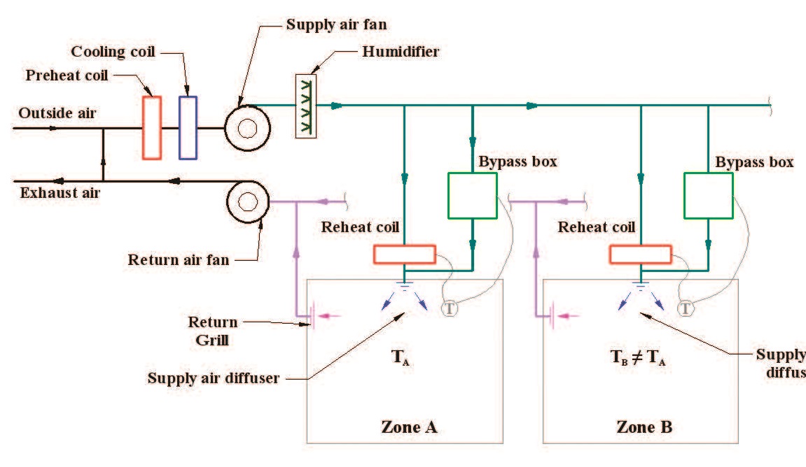
Figure 7. All-air HVAC dual-duct system.
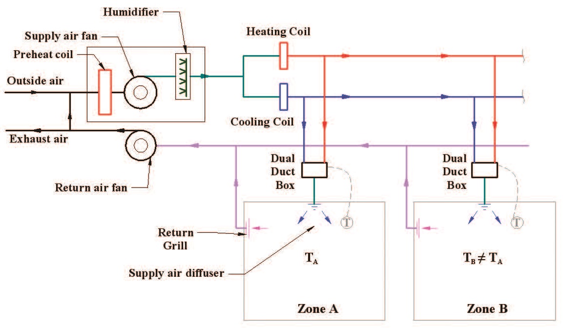
by the air handling unit in separate and parallel ducts. Each zone has a terminal mixing box controlled by zone thermostat to adjust the supply air temperature by mix the supply cold and hot air. This type of system will minimize the disadvantages of previous systems and become more flexible by using terminal control.
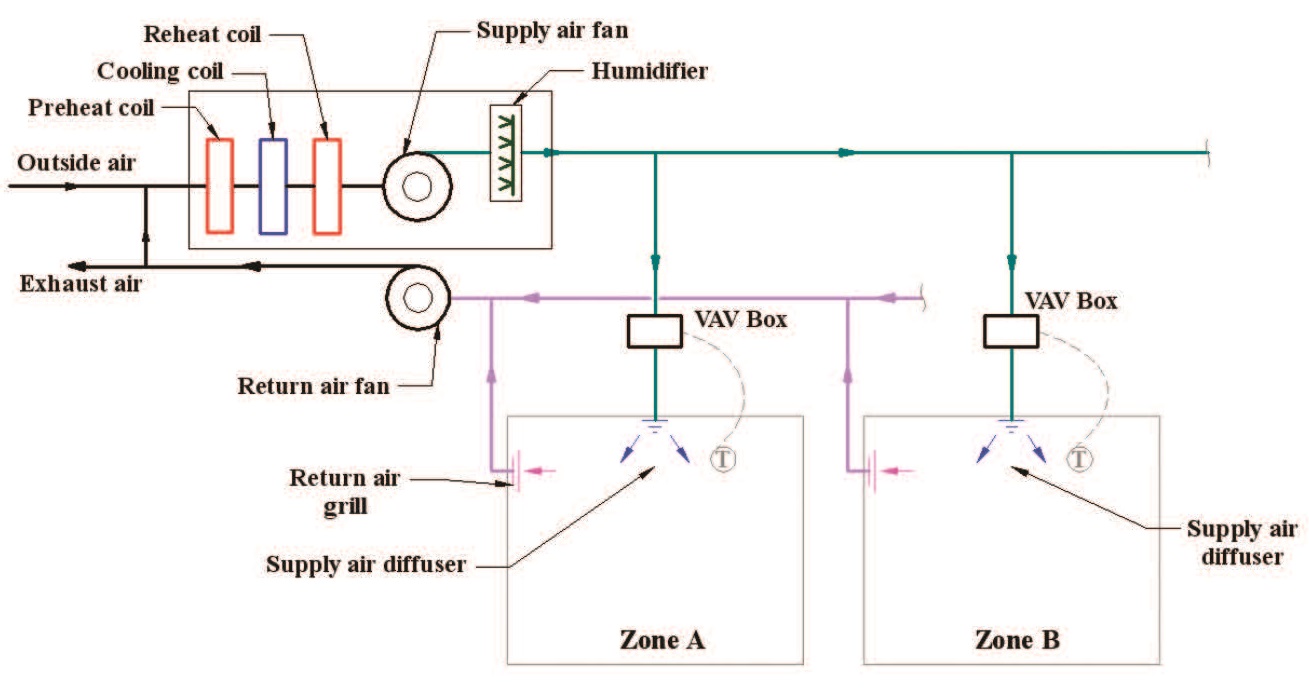
6.1.5. Variable air volume
Some spaces require different airflow of supply air due to the changes in thermal loads. Therefore, a variable-air-volume (VAV) all-air system is the suitable solution for achieving thermal comfort. The previous four types of all-air systems are constant volume systems. The VAV system consists of a central air handling unit which provides supply air to the VAV terminal control box that located in each zone to adjust the supply air volume, as shown in Figure 8. The temperature of supply air of each zone is controlled by manipulating the supply air flow rate. The main disadvantage is that the controlled airflow rate can negatively impact other adjacent zones with different or similar airflow rate and temperature. Also, part-load conditions in buildings may require low air-flow rate which reduces the fan power resulting in energy savings. It may also reduce the ventilation flow rate, which can be problematic to the HVAC system and affecting the indoor air quality of the building.
6.2. All-water systems
In an all-water system, heated and cooled water is distributed from a central system to con-ditioned spaces [4, 5]. This type of system is relatively small compared to other types because the use of pipes as distribution containers and the water has higher heat capacity and density than air, which requires the lower volume to transfer heat. All-water heating-only systems include several delivery devices such as floor radiators, baseboard radiators, unit heaters,
Figure 8. All-air HVAC systems with VAV terminal units.
and convectors. However, all-water cooling-only systems are unusual such as valance units mounted in the ceiling. The primary type that is used in buildings to condition the entire space is a fan-coil unit.
6.2.1. Fan-coil units
Fan-coil unit is considerably small unit used for heating and cooling coils, circulation fan, and proper control system, as shown in Figure 9. The unit can be vertically or horizontally installed. The fan-coil unit can be placed in the room or exposed to occupants, so it is essential to have appropriate finishes and styling. For central systems, the fan-coil units are connected to boilers to produce heating and to water chillers to produce cooling to the conditioned space. The desired temperature of a zone is detected by a thermostat which controls the water
Figure 9. All-water system: fan-coil units.
flow to the fan-coil units. In addition, occupants can adjust fan coil units by adjusting supply air louvers to achieve the desired temperature. The main disadvantage of fan-coils is ventila-tion air and only can be solved if the fan-coil units are connected to outdoor air. Another disadvantage is the noise level, especially in critical places.
6.3. Air-water systems
Air-water systems are introduced as a hybrid system to combine both advantages of all-air and all-water systems [5]. The volume of the combined is reduced, and the outdoor ventilation is produced to properly condition the desired zone. The water medium is responsible for carrying the thermal load in a building by 80–90% through heating and cooling water, while air medium conditions the remainder. There are two main types: fan-coil units and induction units.
6.3.1. Fan-coil units
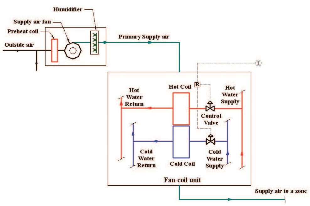
Fan-coil units for air-water systems are similar to that of all-water systems except that the sup-ply air and the conditioned water are provided to the desired zone from a central air handling unit and central water systems (e.g., boilers or chillers). The ventilation air can be separately delivered into space or connected to the fan-coil units. The major types of fan-coil systems, are 2 pipes or 4-pipes systems, as shown in Figure 10.
6.3.2. Induction units
Induction units are externally similar to fan-coil units but internally different. An induction unit induces the air flow in a room through cabinet by using high-velocity airflow from a
Figure 10. Air-water HVAC system using fan coil units with 4-pipes configuration.
central air handling unit, which replaces the forced convection of the fan in the fan-coil by the induction or buoyancy effect of the induction unit, as shown in Figure 11. This can be performed as mixing the primary air from the central unit and the secondary air from the room to produce a suitable and conditioned air into the room/zone.
6.4. Water-source heat pumps
Water-source heat pumps are used to provide considerable energy savings for large build-ing under the extreme cold weather [6]. A building of various zones can be conditioned by several individual heat pumps since each heat pump can be controlled according to the zone control. A centralized water circulation loop can be used as a heat source and heat sink for heat pumps. Therefore, heat pumps can act as the primary source of heating and cooling. The main disadvantage is the lack of air ventilation similar to the all-water systems as in fan-coil units. For a heating process, the boiler or solar collectors will be used to supply heat to the water circulation, while a cooling tower is used to reject heat collected from the heat pumps to the atmosphere. This system does not use chillers or any refrigeration systems. If a building requires a heating process for zones and cooling process for other zones at the same time, the heat pump will redistribute heat from one part to another with no need for a boiler or cooling tower operation,
6.5. Heating and cooling panels
Heating and cooling panels are placed on floors or walls or ceilings where can be a source of heating and cooling. It also can be called as radiant panels. This type of system can be constructed as tubes or pipes impeded inside the surface where the cooling or heating media is circulated into the tubes to cool or heat the surface. The tubes are contacted to the adjacent large surface area to achieve the desired surface temperature for cooling and heating process. The heat transfer process is mainly by the radiation mode between the
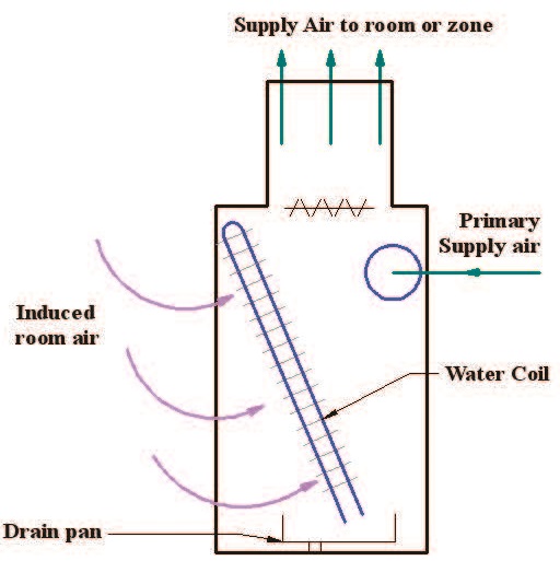
Figure 11. Air-water HVAC system using induction units.
occupants and the radiant panels, and the natural convection mode between the air and panels. Temperature restriction is recommended for radiant floor panels, a range of 66–84°F, to achieve thermal comfort for occupants (ASHRAE Standard 55). Radiant ceiling or wall panels can be used for cooling and heating process. The surface temperature should be higher than the air dew point temperature to avoid condensation on the surface during the cooling process. Also, the maximum surface temperature is 140°F for ceiling levels at 10 ft. and 180°F for ceiling levels at 18 ft. This temperature is recommended to avoid too much heating above occupants’ heads.
The installation of such systems is often expensive compared to other types as mentioned above, but they can be useful and has a lower running cost mainly because of the surface tem-perature restriction. A control signal is connected to the thermostat of each zone to manipulate the medium temperature to condition the space. The used medium can be refrigerant or water mixing with inhibited glycol (anti-freeze) instead of plain water to prevent icing inside the tubes for the cooling process. The main advantage is no space required, only a few inches for the panels to be installed and no more collected dirt in the standard ceiling or the ductwork. Many designs are available to produce attractive panels.
7. Local HVAC systems
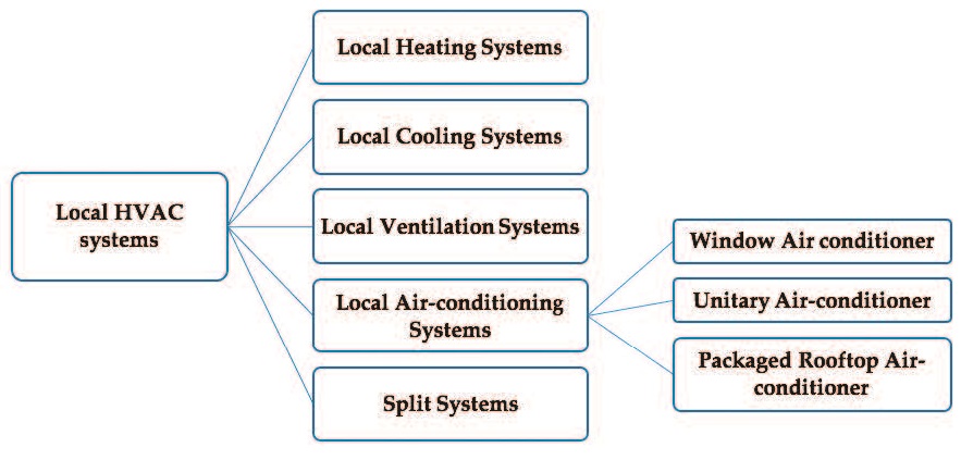
Some buildings can have multiple zones or have a large, single zone, which needs central HVAC systems to serve and provide the thermal needs. However, other building may have a single zone which needs equipment located inside the zone itself, such as small houses and residential apartments. This type of system is considered as local HVAC systems since each equipment serving its zone without crossing boundaries to other adjacent zones (e.g., using an air conditioner to cool down a bedroom, or using an electrical heater for the living room). Therefore, a single zone requires only one-point control point connected to a thermo-stat to activate the local HVAC system. Some buildings have multiple local HVAC systems as proper equipment serving specific single zones and controlled by the one-point control of the desired zone. However, these local systems are not connected and integrated to central systems, but still part of a large full-building HVAC systems. There are many types of local HVAC systems as shown in Figure 12.
7.1. Local heating systems
A single zone will require a complete, single package of heating system which contains heat source and distribution system. Some examples include portable electric heaters, electric resistance baseboard radiators, fireplaces and wood stoves, and infrared heaters.
7.2. Local cooling systems
Local cooling systems can include active systems as air-conditioning systems that provide cooling, a proper air distribution inside a zone, and control of humidification, and natural systems as convective cooling in open window, evaporative cooling in fountains .
Figure 12. Horizontal hierarchy representation of the main types of local HVAC systems.
7.3. Local ventilation systems
Local ventilation systems can be forced systems by using devices such as window fan to allow air movement between outdoor and a single zone without changing in the thermal environ-ment of the zone. Other systems used for ventilation are air circulation devices such as desk or paddle fans to improve thermal comfort of the space by allowing the heat to be transferred by conventional mode.
7.4. Local air-conditioning systems
A local air conditioning system is a complete package that can contain cooling and heating source, a circulation fan, a filter, and control devices. There are three main types listed below.
7.4.1. Window air-conditioner
This system is a packaged device consisting of a vapor compression refrigeration cycle that contains a compressor, a condenser, an expansion valve, and an evaporator, in addition to a fan, a filter, control system and housing. Window air-conditioners can be installed in a framed or unframed opening in building walls and in window openings without any ductwork and distribution the cooling or heating air effectively inside the conditioned space. The air condi-tioning contains both evaporator and condenser where the condenser is located outside the space while the evaporate is inside the space, however, it serves the entire single zone with the thermal requirements. The heating process can be achieved by adding electric resistance coil in the air conditioning or reversing the refrigeration cycle to act as a heat pump. Many feature designs are produced to provide aesthetical values and improve the quality and response.
7.4.2. Unitary air-conditioner
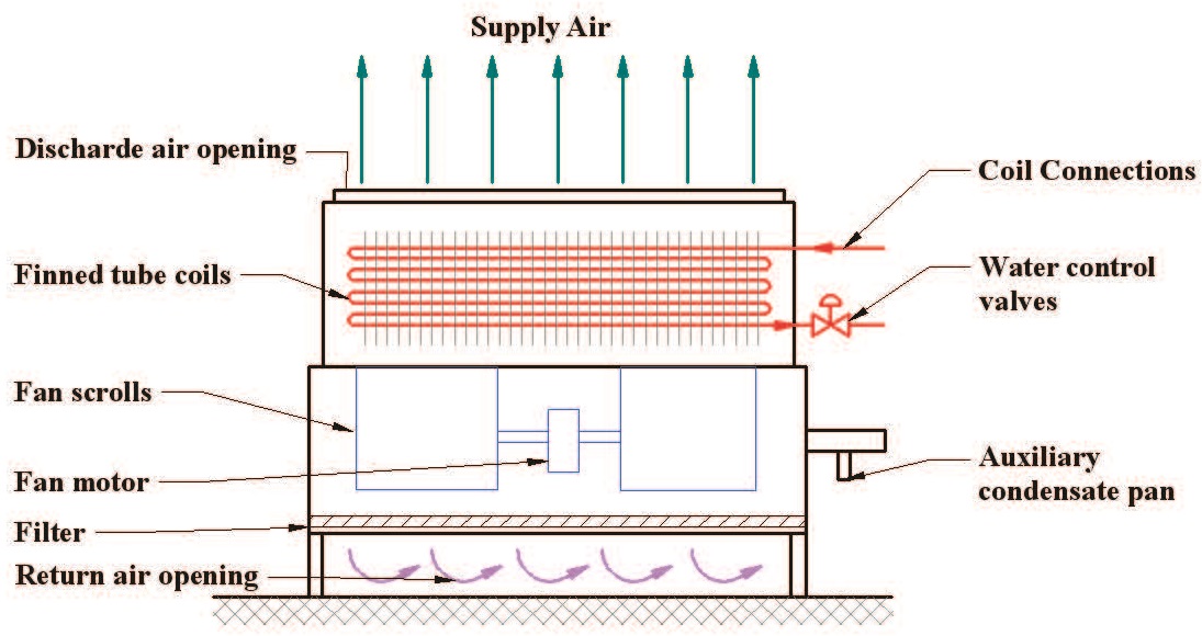
It is similar to window air conditioners from the equipment perspective, but it is designed for commercial buildings. It is installed on the exterior wall of the building and generally located near the floor-wall intersection, as shown in Figure 13. Every single zone will contain one unitary air-conditioner as in each guest room in many hotels.
7.4.3. A packaged rooftop air-conditioner
It consists of a vapor compression refrigeration cycle; heat source such as heat pump and electric resistance; an air handler such as dampers, filter, and fan; and control devices, as shown in Figure 14. This system may be connected to ductwork and serve a large-size single zone that cannot be served by unitary or window air conditioners.
7.5. Split systems
The split systems contain two central devices: the condenser, located outdoor, and the evaporator, located indoors. The two devices are connected by a conduit for refrigerant lines and wiring. This system solves some issues of small-scale single-zone systems since the loca-tion and installation of window, unitary or rooftop air conditioners may affect the esthetic value and architectural design of the building. The split systems can contain one condenser unit and connected to multiple evaporator units to serve multiple zones as possible under same conditions or different environmental conditions.
Figure 13. Unitary air-conditioner package
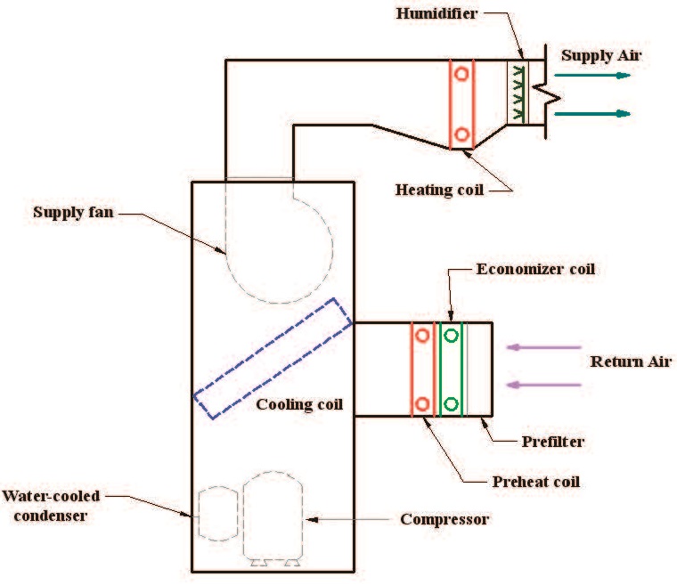
Figure 14. Packaged rooftop air-conditioning unit.
8. Conclusions
This chapter presents the types of HVAC systems. HVAC systems have several requirements including primary equipment such as heating equipment, cooling equipment, and delivery equipment; space requirement such as HVAC facilities, equipment room, and vertical shaft; air distribution; and piping. Type of HVAC systems can be divided into central HVAC sys-tems and local HVAC systems. This classification depends on zone types and the location of HVAC equipment. The central HVAC systems can serve multiple and single zones and locate away from the building, which needs distribution devices. They also can be sub-classified into all-air HVAC systems, air-water systems, all-water systems, water-source heat pumps, and heating and cooling panel systems. The local HVAC systems are mostly placed inside or adjacent to the living spaces and serve one single zone. They consist of local heating systems, local air-conditioning systems, local ventilation systems, and split systems.